


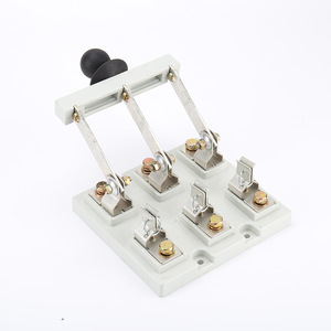


Types of DC Isolator Switch 200A
According to the DC isolator switch 200A handbook, isolators can be categorized based on their operation method and terminal design. Understanding these variations helps in selecting the right isolator for your specific application.
Expert Advice: When selecting a DC isolator switch, consider not only the current rating but also the environmental conditions where it will be installed. For outdoor applications like solar systems, choose isolators with higher IP ratings to protect against moisture and dust.
Operation Method Categories
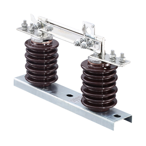
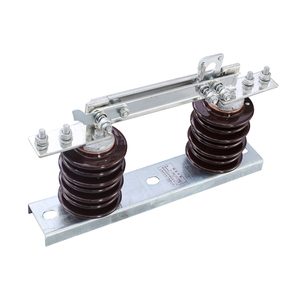
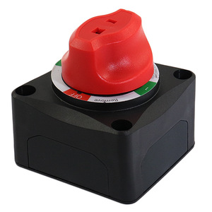
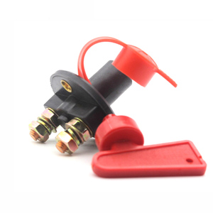
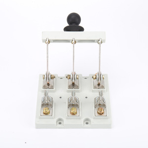
Hand-operated 200A DC Isolator Switch
Manually controlled via handle or lever. Ideal for situations requiring infrequent operation or where simple, low-cost solutions are needed. These switches require minimal maintenance and are generally more economical.
Best for: Cost-effective solutions, low-frequency switching operations
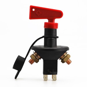
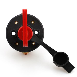
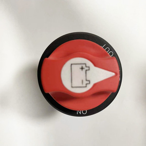
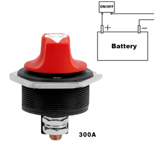
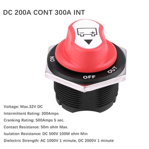
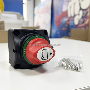
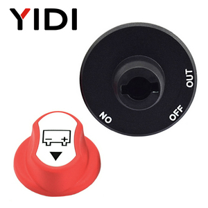
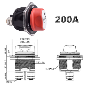
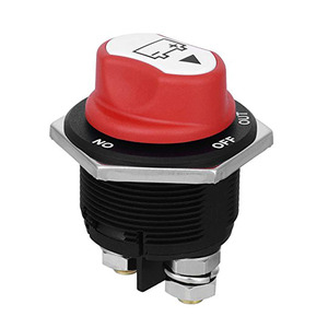
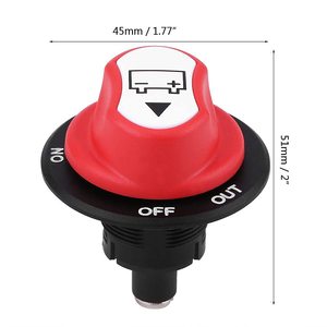
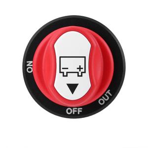
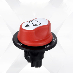
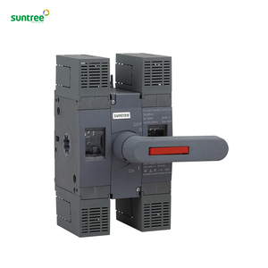
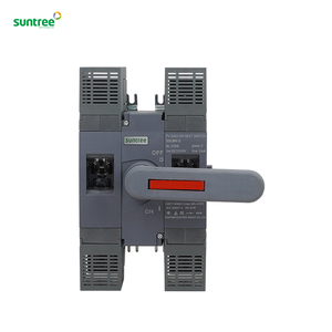
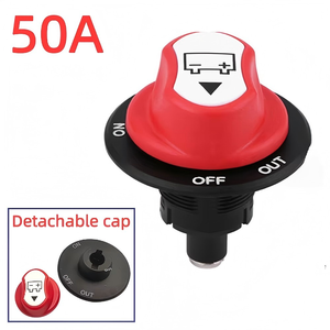
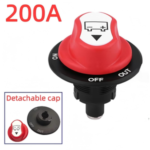
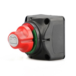
200A Rotating Isolator Switch
Features a round switch that rotates to open and close the circuit. The switch face typically includes clear ON/OFF position indicators, providing intuitive operation and visual confirmation of the switch state.
Best for: Applications requiring visual confirmation of switch position
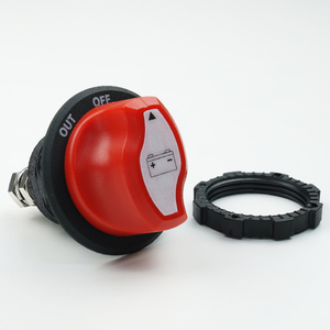
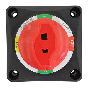
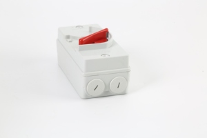
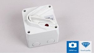
200A Flick Switch
Similar to a standard wall light switch with a toggle mechanism that flips up and down. This design enables quick and easy circuit control, making it suitable for applications requiring frequent operation or rapid switching.
Best for: Frequent operation, quick switching requirements
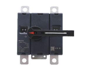
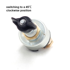
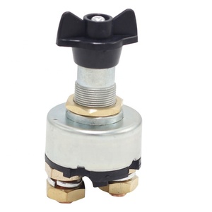
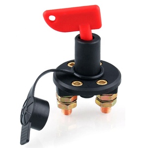
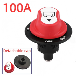
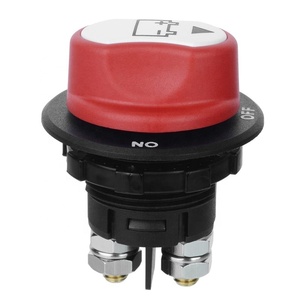
200A Rotary DC Switch
Hand-operated switch requiring rotation to operate. May feature a lever, knob, or paddle depending on design. Provides precise control and adjustments as needed, with defined positions for circuit states.
Best for: Precise control applications, multiple position requirements
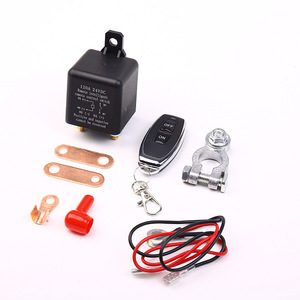
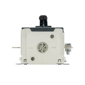
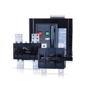
200A Push-button Isolator Switch
Controlled via push buttons - typically one to open, one to close, and potentially a third for reset or emergency stop. Allows for remote control and integration with automated systems for enhanced safety.
Best for: Remote control applications, safety-critical systems
Terminal Design Categories
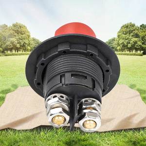
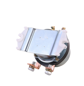
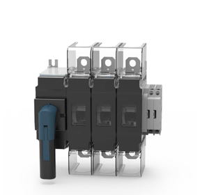
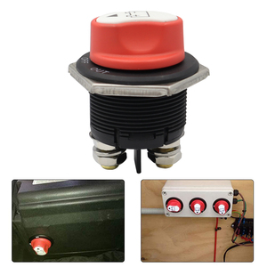
200A Slip-on Terminal Isolator Switch
Features connections where wires slide onto terminals and are secured with screws or clamps. Provides reliable connections but requires periodic inspection to ensure good contact and conductivity.
Best for: Applications with occasional maintenance access
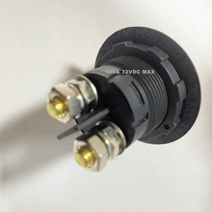
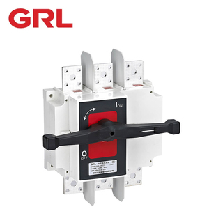
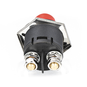
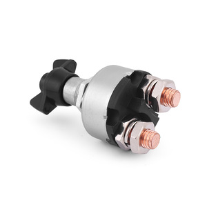
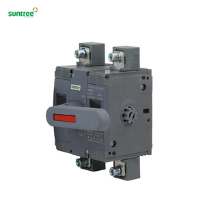
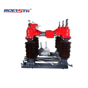
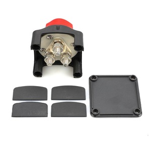
200A Bolted Terminal Isolator Switch
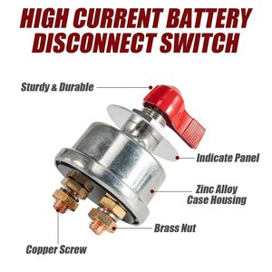
Uses bolted connections for attaching wires or conductors to terminals. Provides more secure and reliable connections than slip-on terminals, making it suitable for high-current or critical applications.
Best for: High-current applications, critical systems requiring maximum reliability
| Isolator Type | Operation Method | Best Applications | Key Advantages |
|---|---|---|---|
| Hand-operated | Manual lever/handle | Low-frequency switching | Cost-effective, simple maintenance |
| Rotating | Circular rotation | General purpose applications | Clear position indication, intuitive use |
| Flick Switch | Toggle up/down | Frequent switching needs | Quick operation, familiar design |
| Rotary | Rotation with lever/knob | Precision control requirements | Precise adjustments, multiple positions |
| Push-button | Button press | Automated systems | Remote control capability, safety features |
| Slip-on Terminal | Varies by switch type | Standard installations | Easy connection, reasonable security |
| Bolted Terminal | Varies by switch type | Critical, high-current systems | Maximum connection security, reliability |
Specifications and Maintenance of DC Isolator Switch 200A
Understanding the key specifications and proper maintenance procedures for 200A DC isolator switches is crucial for ensuring safety, reliability, and longevity in electrical systems.
Key Specifications of 200A DC Isolator Switches
| Specification | Typical Values/Descriptions | Importance |
|---|---|---|
| Current Rating | 200 Amperes | Defines maximum continuous current handling capacity |
| Voltage Rating | 600 VDC to 1000 VDC | Determines maximum voltage the switch can safely isolate |
| Pole Configuration | 2-pole or 4-pole | Affects circuit isolation capabilities and applications |
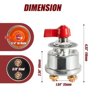
| Mounting Options | Wall or panel mounting | Impacts installation flexibility and accessibility |
| Enclosure Rating | IP65 to IP67 | Defines protection level against dust and water ingress |
| Terminal Connections | Bolted or quick-connect | Affects installation ease and connection reliability |
| Operating Temperature | -40°C to 85°C | Determines environmental operating conditions |
| Standards Compliance | IEC 60947-3, UL 508 | Ensures safety and performance requirements are met |
| Short-Circuit Current Rating | System-dependent | Critical for protecting against fault conditions |
| Mechanical Life | Typically 10,000+ operations | Indicates durability before mechanical failure |
| Electrical Life | Typically 1,000+ operations under load | Indicates performance longevity under electrical stress |
Safety Warning: Always ensure the system is completely de-energized before performing any maintenance on DC isolator switches. Verify isolation using appropriate testing equipment before beginning work.
Essential Maintenance Procedures
Proper maintenance of 200A DC isolator switches is crucial for ensuring continued safe operation and maximizing service life. Implement these maintenance practices according to manufacturer recommendations and system criticality.
| Maintenance Task | Recommended Frequency | Procedure Details |
|---|---|---|
| Visual Inspection | Monthly | Check for signs of physical damage, corrosion, discoloration, or heat damage on the switch body and terminals |
| Operation Check | Quarterly | Test switch operation to ensure smooth action without sticking or excessive resistance |
| Electrical Connection Inspection | Semi-annually | Verify all connections are tight; look for signs of arcing, heating, or loose terminals |
| Cleaning | Quarterly | Remove dust and debris using soft brush or clean cloth; avoid liquid cleaners on internal components |
| Lubrication | Annually or per manufacturer | Apply appropriate lubricant to mechanical parts as specified by manufacturer |
| Thermal Imaging | Annually | For critical installations, perform thermal imaging to detect hotspots indicating potential problems |
| Load Testing | Annually | Verify switch performance under normal operating conditions |
| Environmental Assessment | Quarterly | Check that environmental conditions remain within switch specifications |
| Complete Replacement | Per manufacturer guidelines or condition | Replace switch when it reaches end of mechanical/electrical life or shows signs of degradation |
Maintenance Tip: Document all maintenance activities, including date, findings, and actions taken. This maintenance history is invaluable for predicting failure patterns and optimizing maintenance schedules.
How to Choose DC Isolator Switch 200A
Selecting the appropriate 200A DC isolator switch requires careful consideration of technical specifications, environmental factors, and application requirements. This guide will help you make an informed decision to ensure optimal performance and safety.
Critical Selection Factors for 200A DC Isolator Switches
Voltage and Current Ratings
The isolator must have voltage and current ratings that meet or exceed your system requirements. For high-current applications like solar arrays, select a switch with at least 20% headroom above maximum expected current to prevent overheating.
Key consideration: System voltage (e.g., 600V, 1000V, 1500V) and maximum current flow
System Compatibility
Ensure compatibility with your specific electrical system design. For example, PV solar installations may require specialized DC isolators that can handle the particular characteristics of solar power systems.
Key consideration: Application type (solar, battery storage, EV charging, etc.)
Endurance Ratings
Consider both mechanical and electrical endurance specifications. Mechanical endurance indicates physical operation cycles before failure, while electrical endurance shows performance under load before degradation.
Key consideration: Expected switching frequency and operational lifespan
Safety Standards & Certifications
Verify compliance with relevant industry standards such as IEC61850 for substation automation or UL508 for industrial control equipment. These certifications ensure the switch meets safety and performance requirements.
Key consideration: Regional electrical codes and specific industry requirements
Environmental and Application Considerations
Beyond technical specifications, these factors should influence your isolator switch selection:
| Selection Factor | Considerations | Recommended Features |
|---|---|---|
| Indoor vs. Outdoor Installation | Exposure to elements, temperature variations, UV radiation | Higher IP rating (IP66+), UV-resistant materials, wider temperature range |
| Harsh Environments | Corrosive atmospheres, high humidity, salt exposure | Corrosion-resistant materials, sealed enclosures, specialized coatings |
| Accessibility | Ease of operation, maintenance access | Ergonomic handles, front access terminals, clearly visible indicators |
| Safety Requirements | Prevention of unauthorized operation, emergency shutdown | Lockable handle, clear ON/OFF markings, emergency stop capability |
| Installation Method | Mounting options, space constraints | Compatible mounting brackets, compact design if space-limited |
| Integration with Monitoring | Remote status monitoring, system integration | Auxiliary contacts, compatibility with monitoring systems |
| Cost Considerations | Initial cost vs. long-term reliability | Balance quality with budget; prioritize safety features |
Selection Tip: When choosing between different 200A DC isolator switches, consider the total cost of ownership rather than just the initial purchase price. A higher-quality isolator may cost more upfront but can provide better reliability, longer service life, and reduced maintenance costs over time.
How to DIY and Replace DC Isolator Switch 200A
Replacing a DC isolator switch 200A requires basic electrical knowledge and careful attention to safety procedures. Follow this step-by-step guide to safely and effectively replace your isolator switch.
Safety Warning: Working with electrical systems carries inherent risks. If you're unsure about any step in this process, consult a qualified electrician. Always verify the system is completely de-energized before beginning work.
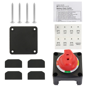
Tools and Materials Needed
- New 200A DC isolator switch (compatible with your system)
- Screwdrivers (flathead and Phillips)
- Wire cutters/strippers (if rewiring is needed)
- Electrical tape
- Digital multimeter or voltage tester
- Personal protective equipment (insulated gloves, safety glasses)
- Camera or smartphone (for documenting original connections)
- Terminal crimping tool (if applicable)
- Appropriate mounting hardware
Step-by-Step Replacement Process
-
Safety Preparations
Turn off all connected power sources. For solar systems, this includes turning off solar inverters and AC supply. Cover solar panels if possible or work during low-light conditions. Put on appropriate personal protective equipment.
-
Verify Power Isolation
Use a multimeter or voltage tester to confirm zero voltage at the isolator terminals. Test all terminals to ensure the system is completely de-energized before proceeding.
-
Document Original Connections
Take clear photos of the existing wiring configuration from multiple angles. Note wire colors, terminal positions, and any labeling to ensure correct reconnection later.
-
Disconnect Wiring
Carefully loosen terminal screws and disconnect all wires from the old isolator. Ensure wires don't touch each other or other conductive surfaces. Label wires if necessary for clear identification.
-
Remove Old Isolator
Unscrew the mounting hardware securing the old isolator to its mounting surface. Carefully remove the old unit, noting its orientation and position.
-
Prepare Mounting Location
Clean the mounting surface and ensure it's free of moisture or debris. If new mounting holes are needed, mark and drill them according to the new isolator's specifications.
-
Mount New Isolator
Position the new 200A DC isolator switch in the same orientation as the old one. Secure it firmly using appropriate mounting hardware, ensuring it's level and properly supported.
-
Connect Wiring
Following your documentation from step 3, reconnect wires to the appropriate terminals on the new isolator. Ensure terminal screws are tightened to the manufacturer's torque specifications to prevent loose connections.
-
Final Inspection
Double-check all connections for tightness and correct positioning. Ensure no stray wire strands are exposed or touching other terminals. Verify the switch is in the OFF position before restoring power.
-
Operational Testing
Restore power to the system gradually. Once powered, carefully test the operation of the new isolator by switching it ON and OFF several times to ensure smooth operation without sparking or unusual resistance.
Installation Tip: When connecting wires to the new isolator, apply a thin layer of dielectric grease to terminal connections in outdoor or humid environments. This helps prevent corrosion and ensures long-term reliability of the electrical connections.
Post-Installation Checklist
- Verify there is no abnormal heating at terminal connections under normal load
- Check that the isolator handle operates smoothly without excessive force
- Ensure the isolator enclosure is properly sealed against environmental ingress
- Confirm all safety markings and labels are in place and clearly visible
- Document the replacement date and new isolator specifications for maintenance records
- Schedule a follow-up inspection after one week of operation to check for any issues
Frequently Asked Questions
Where is a DC isolator switch 200A needed?
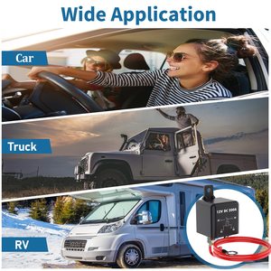
DC isolator switches rated at 200A are essential in high-current DC electrical systems where safe disconnection capabilities are required. They're commonly installed in these applications:
- Solar Power Systems: Used to disconnect PV arrays from inverters for maintenance or emergency shutdown
- Commercial Electrical Installations: For isolating high-current DC circuits in industrial settings
- Residential Solar Arrays: Larger residential installations with higher current outputs
- Battery Storage Systems: To safely isolate battery banks during maintenance
- Wind Energy Systems: For disconnecting DC power from turbines
- EV Charging Stations: High-capacity DC fast charging installations
- Telecommunications: For DC power systems in communication infrastructure
These isolators provide a visible and lockable point of isolation, crucial for ensuring safety during maintenance operations and compliance with electrical codes and standards.
Why is a 200A isolator switch used?
A 200A DC isolator switch is specified for applications with high current demands for several important reasons:
Current Handling Capacity
The 200A rating indicates the switch can safely handle continuous current flow up to 200 amperes without overheating or sustaining damage. This makes it suitable for large solar arrays, industrial equipment, and other high-power DC applications.
Safety Margin
Even in systems with typical operating currents below 200A, the higher rating provides a safety margin for current spikes, future system expansions, or operation in high-temperature environments where derating may be necessary.
The substantial current rating also ensures the switch can safely interrupt the circuit under load without dangerous arcing or contact damage, which is particularly important in DC systems where arc extinction is more challenging than in AC systems.
Do isolator switches require a circuit breaker?
No, isolator switches do not require circuit breakers, but they serve complementary functions in electrical systems:
| Feature | Isolator Switch | Circuit Breaker |
|---|---|---|
| Primary Function | Provides visible isolation for maintenance safety | Provides overcurrent and short-circuit protection |
| Operation Under Fault | Not designed to interrupt fault currents | Automatically interrupts during fault conditions |
| Typical Installation | Upstream of circuit breakers or alongside them | Downstream of isolators in distribution systems |
| Load Breaking | Some are load-break rated, others are not | Designed specifically for breaking under load |
In most electrical installations, isolator switches and circuit breakers work together as part of a comprehensive protection and isolation strategy, with the isolator providing safe disconnection for maintenance after the circuit breaker has interrupted the circuit.
Can an isolator switch be installed in any position?
While technically an isolator switch can be installed in various positions, there are important considerations that should guide optimal positioning:
- Manufacturer Guidelines: Always follow the manufacturer's installation instructions regarding mounting orientation. Some switches are designed for specific mounting positions.
- Accessibility: The switch should be positioned for easy operation, with clear access to the handle or operating mechanism without requiring awkward reaching or positioning.
- Visibility: The switch position (ON/OFF) should be clearly visible to operators for safety verification.
- Environmental Protection: In outdoor installations, consider orientation that minimizes water ingress through seals or cable entries.
- Heat Dissipation: Ensure the position allows adequate ventilation, particularly for switches handling currents near their rated capacity.
- Cable Management: Position should accommodate proper cable routing without excessive bending or stress on connections.
- Compliance with Codes: Local electrical codes may specify mounting height or accessibility requirements, particularly for emergency disconnection means.
The ideal installation position balances these factors to ensure safe operation, longevity of the equipment, and compliance with relevant standards and regulations.


 浙公网安备 33010002000092号
 浙B2-20120091-4